10+ Chiller System Diagram
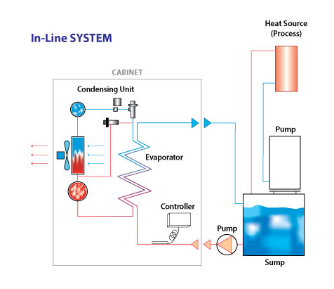
Unlike air chillers the water systems can be installed in an indoor environment or any sealed room. The compressor the condenser the expansion valve and the evaporator.
Chiller What Is It How Does It Work Types Uses
With a wide range of air-cooled chiller scroll and screw types capacities 10 to 500 tons and sustainable refrigerant options Carrier is a leader in.

. Thus chillers can use two different types of. Chilled water system diagram photos A chilled water system can be separated into two loops. Industrial water or glycol chiller systems contain two main circuits.
It can be used for Chilled Water in sites such Industrial cooling Process chilling hotel hospital mall. Chiller Basics The chiller can be water cooled or air cooled. Combined Process Chiller to constitute various Industrial Chilling system.
These diagrams show how the different components of the system connect to one another and how the connections are made. Web Types of Chillers. Web With solutions from 10 through 500 tons screw or scroll Carrier air-cooled chillers are the best choice for your needs.
This manual discusses the chillers evaporator and condenser and their relationship to the chilled-water plant. Web Chiller System Schematic Diagrams are essential for understanding how chiller systems work. But the real magic happens in the chiller itself.
For normal air conditioning applications the chiller can adjust capacity from 100 to 10 of design without the use of hot gas bypass HGBP. Web Chilled water system diagram. Web 151 Refrigeration Circulating System - 10 - 152 Oil Circulating System - 11 - 16 Introduction of Control System - 12 - 2 Installation - 14 -.
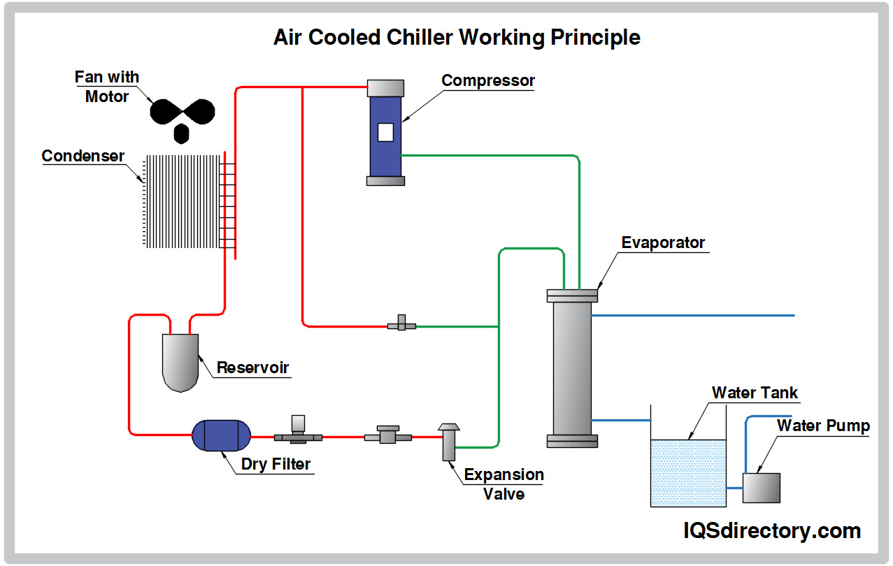
Once this is done you will be able to troubleshoot the system more quickly and effectively. Major vapor- compression chiller components include an evaporator compressors condenser and expansion devices Figure 1. Take note of each components function location and connections.
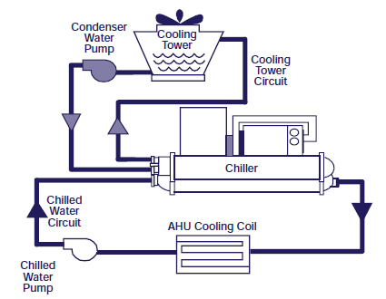
The system consists of a chiller cooling tower building cooling load chilled water and condensing water pumps and piping. Web purposes of discussion chilled water pumping systems are divided into three categories. It is the ideal option for those who need a cooling system but does not.
What Water Cooled Chiller Diagram to Install. Web See the attached diagram which outlines the key components of the chiller system. Web A schematic diagram is a technical drawing that shows how each component of a chiller system is connected and functions together.
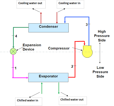
PrimarySecondary Chilled Water Systems 3. Web The diagram shows the flow of refrigerant which absorbs heat from the chilled water and carries it to the condenser. When designing a chilled-wat er system one of the first issues that must be addressed is to determine which type of water chiller to use.
As described two different cooling mediums air or water can facilitate the transfer of the latent heat given up as the refrigerant changes from vapor to liquid. Figure 1 shows the basic centrifugal refrigeration circuit. Web Major vapor-compression chiller components include an evaporator a compressors a condenser and an expansion devices.
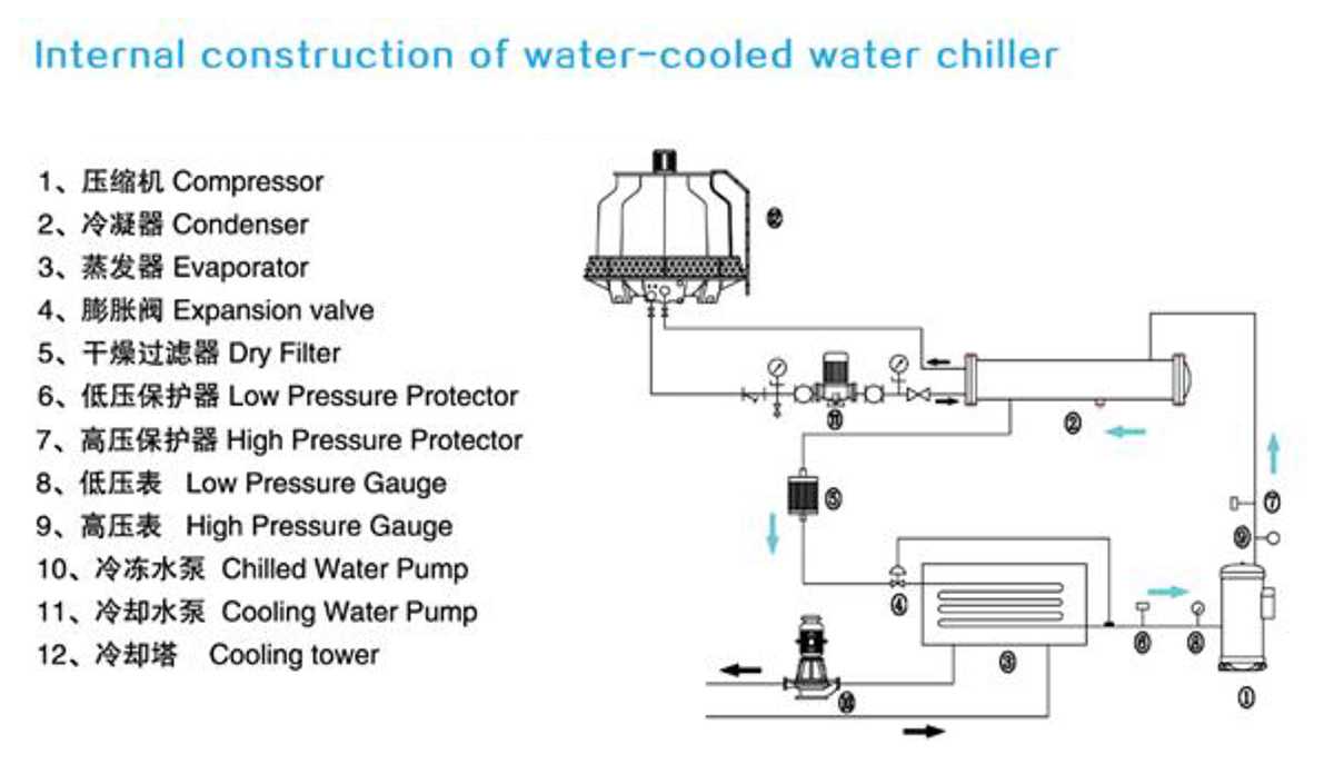
Among them the centrifugal chiller is the most common type of chiller in HVAC. Diagram showing the components of a liquid-cooled chiller A view into the exposed shell and tube heat exchanger on a centrifugal chiller. They provide a visual representation of the components and their connections allowing technicians to diagnose issues and make repairs quickly and efficiently.
Web The best way to use a chiller system schematic diagram is to familiarize yourself with the layout of the system and its components. This period discusses the primary differences in chiller types. Web Major vapor-compression chiller components include an evaporator a compressors a condenser and an expansion devices.
Web The cooling system diagram for an air-cooled chiller typically includes an air-cooled condenser compressor evaporator and expansion valve. Chillers transfer heat away from a space that requires climate control much like a traditional split system or package unit does but they use water or a water solution to do so instead of air. Web YZ technology matches chiller system components to provide maximum chiller efficiency under actual not just theoretical operating conditions.
Figure 1 Typical vapor-compression chiller Condenser Evaporator Compressor. Most of the time chillers are categorized as either water-cooled or air-cooled. Web Chiller schematic diagrams are also known as wiring diagrams and provide an illustration of the components of a chiller system and the wiring that connects them.
Web Basic System Figure 1 shows a basic chilled water system with connected loads. Web Water Chiller System. Systems that employ water chillers are commonly called chilled-water systems.
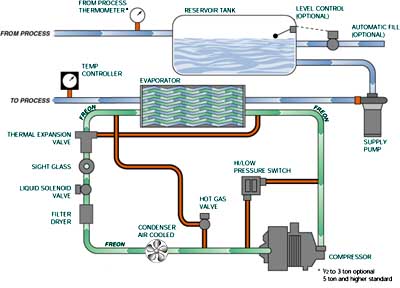
For each condition the capacity control. The refrigeration circuit removes heat from the process fluid. The refrigeration circuit is made up of four components.
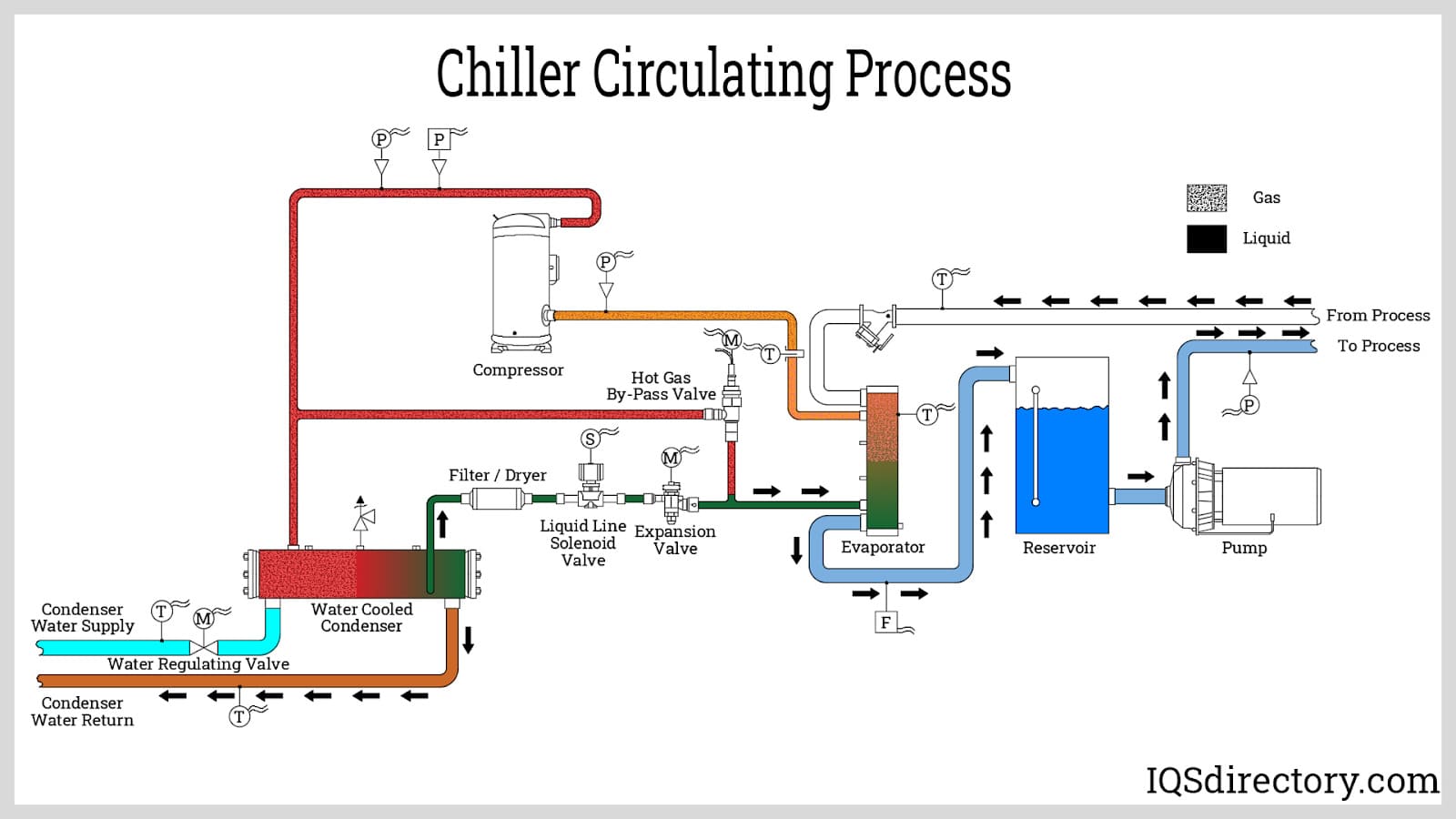
Web A centrifugal chiller utilizes the vapor compression cycle to chill water and reject the heat collected from the chilled water plus the heat from the compressor to a second water loop cooled by a cooling tower. The diagram includes all of the major components such as the compressor evaporator condenser expansion valve. A chilled water loop and b condenser water loop.
From there the heat is released into the atmosphere and the refrigerant is pumped back to the evaporator to start the process again. Instead of just blocks with texts here is the same diagram but with actual photos. A refrigeration circuit and a fluid circuit.
Constant Volume Chilled Water Systems 2. Figure 1 Typical vapor-compression chiller Condenser Evaporator Compressor. Web Chillers can be either air- or water-cooled.
This manual discusses the chillers evaporator and condenser and their relationship to the chilled-water system. This section will review each of the components. Variable Primary Flow Chilled Water Systems.
A comprehensive schematic diagram can be an invaluable tool for technicians. Web How Do Chillers Work. Web The 5 common types of chillers in HVAC are the centrifugal chiller the air-cooled chiller the hybrid chiller the magnetic bearing chiller and the heat recovery chiller.
The condenser and evaporator are connected by refrigerant lines allowing the refrigerant to. Before we move further lets briefly refresh the basic hydronic principles. This manual discusses the chillers evaporator and condenser and their relationship to the chilled-water plant.

Air Cooled Chiller System And Water Cooled Chiller Unit Difference

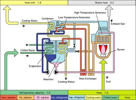
Basics For Absorption Chillers 2009 03 01 Engineered Systems Magazine
Water Chiller Animated Schematic Typical 2 30 Tons Air Cooled
10hp Water Cooled Chiller What We Do Shandong Mgreenbelt Machinery Co Ltd
The Ultimate Guide To Chiller Systems Everything You Need To Know
Iceman Sc Series Portable Chiller Mokon Temperature Control Units
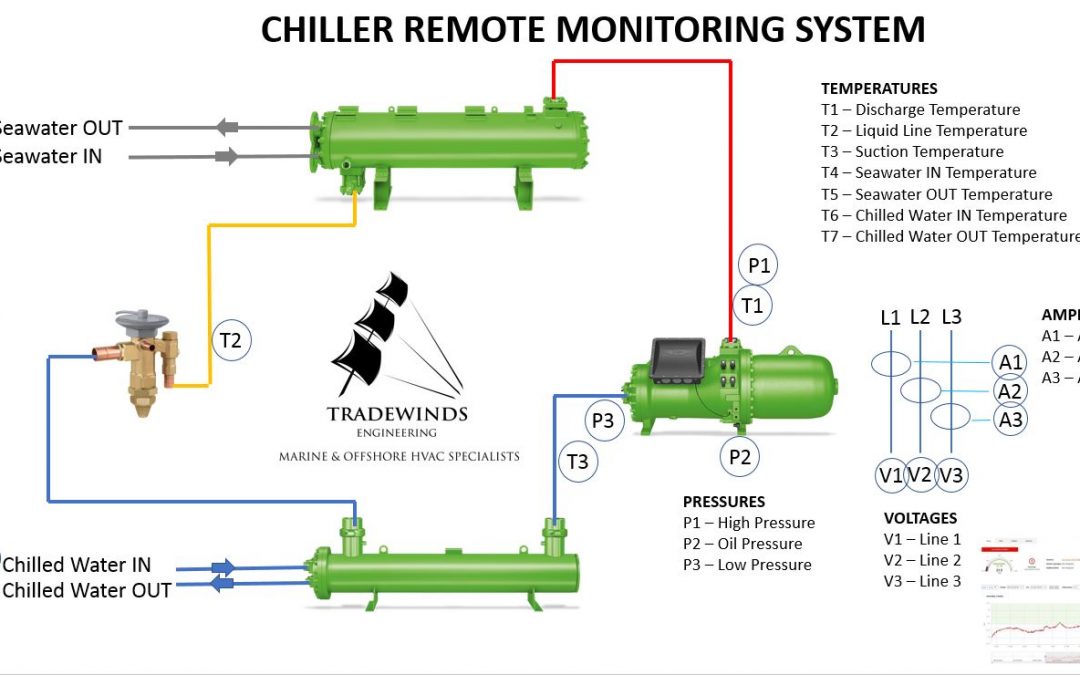
Chiller Monitoring System Yacht And Marine Refrigeration Services
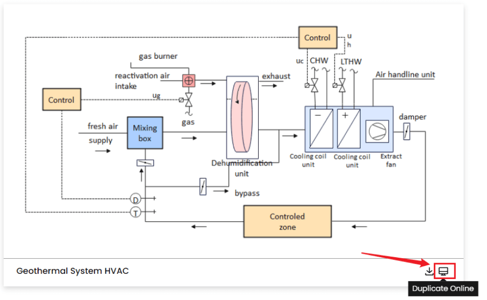
Free Editable Hvac Plan Examples Templates Edrawmax
The Bas Professional S Guide To Central Cooling Plants

Schematic Of A Typical Chilled Water System Download Scientific Diagram
Absorption Chiller Schematic Diagram Download Scientific Diagram
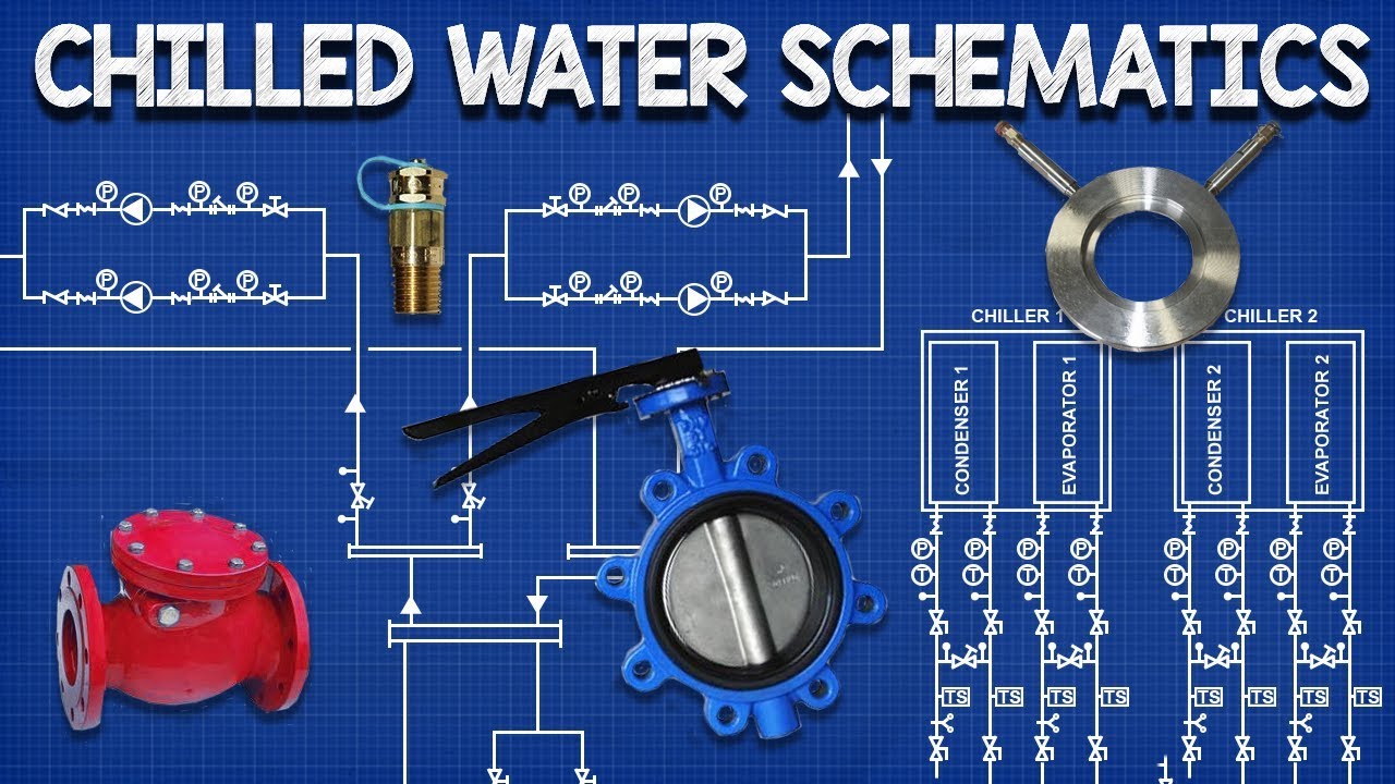
Chilled Water Schematics How To Read Hvac Engineering Drawing Diagram Youtube

Top 10 Temperatures You Should Know About Water Chiller Systems
Chiller Overview Turmoil Inc
Air Cooled Chillers Principle Types Applications And Benefits

Wholesale 40hp Industrial Water Cooled Chiller With Sanyo Or Copeland Compressor From M Alibaba Com
Heating And Cooling System Upgrades Energy Models Com